|
|
EIDORS: Electrical Impedance Tomography and Diffuse Optical Tomography Reconstruction Software |
|
EIDORS
(mirror) Main Documentation Tutorials − Image Reconst − Data Structures − Applications − FEM Modelling − GREIT − Old tutorials − Workshop Download Contrib Data GREIT Browse Docs Browse SVN News Mailing list (archive) FAQ Developer
Hosted by |
The effect of contact impedanceThe contact impedance parameter fmdl.electrode(idx).z_contact controls the impedance of the material out of which the electrode is contructed. z_contact is not the impedance of the electrode cable. It also has no effect for point electrode models.Simulation Model
Elec_width= 10; % 2 degrees - electrode width
params = [ 20,10,2]./[1000,1,100]; %d4
ea = Elec_width/2 *(2*pi/360);
n_elec= 4;
for i=1:n_elec(1);
  ai = (i-1)/n_elec(1) * 2*pi;
  elec_pts{i} = [sin(ai+ea),cos(ai+ea);sin(ai-ea),cos(ai-ea)];
end
fmdl= dm_2d_circ_pt_elecs( elec_pts, [], params);
subplot(221); show_fem(fmdl); axis image
print_convert contact_impedance01a.png
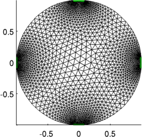
Figure: A 2D finite element model with four electrodes and current simulation across horizontal pairs. fmdl.stimulation(1).stim_pattern = [0;1;0;-1]; fmdl.stimulation(1).meas_pattern = [0;1;0;-1]'; fmdl.solve = @fwd_solve_1st_order; fmdl.system_mat = @system_mat_1st_order; fmdl.electrode(1).z_contact = 0.01; img = mk_image(fmdl,1); img.fwd_solve.get_all_meas = 1; vh = fwd_solve(img); imgv= rmfield(img,'elem_data'); imgv.node_data = vh.volt; show_fem(imgv); axis([-1.1,1.1,-0.5,0.5]); print_convert contact_impedance02a.png 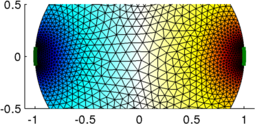
Figure: Voltage distribution from horizontally opposite stimulation Current Near Top Electrode
imgc= img;
imgc.fwd_model.mdl_slice_mapper.npx = 128;
imgc.fwd_model.mdl_slice_mapper.npy = 200;
imgc.fwd_model.mdl_slice_mapper.level = [inf,inf,0];
hh=show_fem(imgc);
set(hh,'EdgeColor',[1,1,1]*.75);

 hold on;
q = show_current(imgc,vh.volt);
quiver(q.xp,q.yp, q.xc,q.yc,15,'b','LineWidth',1);
axis([-.2,.2,0.8,1.05]);
hold off;

title(sprintf('current near electrode:  zc = %5.3f',fmdl.electrode(1).z_contact));
print_convert contact_impedance03a.png
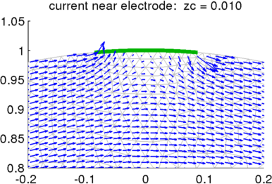
Figure: Current near top electrode Current Stream Lines
ci = [5 .5 .05];
for i=1:3
   img.fwd_model.electrode(1).z_contact=ci(i);
   vh = fwd_solve(img);
   imgc.fwd_model.mdl_slice_mapper.xpts = linspace(-0.25,0.25,200);
   imgc.fwd_model.mdl_slice_mapper.ypts = linspace(0.8,1,100);
   q = show_current(imgc,vh.volt);
   hh=show_fem(imgc);
   set(hh,'EdgeColor',[1,1,1]*.75);
   hold on;

   sy = linspace(.98,.8 ,20); sx= 0*sy - 0.15;
   hh=streamline(q.xp,q.yp, q.xc, q.yc, sx,sy); set(hh,'Linewidth',2);
   hh=streamline(q.xp,q.yp,-q.xc,-q.yc,-sx,sy); set(hh,'Linewidth',2);

   title(sprintf('streamlines zc = %5.3f',fmdl.electrode(1).z_contact));
   hold off;
   axis([-.15,.15,0.85,1.02]);

   title(sprintf('current near electrode:  zc = %5.3f',ci(i)));
   print_convert(sprintf('contact_impedance04%c.png','a'+i-1));
end
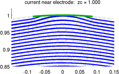
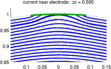
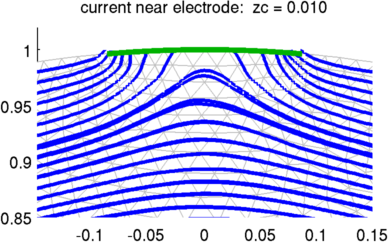
Figure: Current near top electrode for three different z_contact values |
Last Modified: $Date: 2017-02-28 13:12:08 -0500 (Tue, 28 Feb 2017) $ by $Author: aadler $