| |
BIOM 5200 - Assignment #3
-
Display of Medical Image Data
Software for viewing of medical images typically
provides a "windowing" function. Windowing performs
a linear stretching of the image histogram, in order
to better view pixels with values in the "window".
For example, if the screen pixels have intensities
in the range 0 to 255, a windowing from
wmin
to
wmax
will convert a pixel f to a value of
255 × (f - wmin ) /
( wmax − wmin )
on the output display. Details of f above or below this
range are eliminated and f is set to a displayed value of
255 or 0, respectively. Windowing serves two important functions:
1) it enhances the visibility of contrasting tissue regions, 2)
it allows selection of the tissue type to be viewed (for example,
with CT images, windowing can allow viewing of soft tissue while bone
regions are "cropped" to the maximum or minimum value)
-
Describe how "windowing" allows these goals to be
achieved
-
Describe how the visibility of contrasting regions
in an image
varies with the size of the contrasting region and the
SNR.
-
Describe how "windowing" interacts with the
variation in visibility with SNR.
Considering these effects, what image
conditions (in terms of contrast size and SNR)
benefit most from "windowing"?
-
Nuclear Medical Imaging
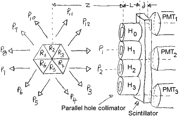
Consider the SPECT system of the figure below.
Six triangular
regions are defined (R1 to R6)
from which twelve projections measurements are made
(P1 to P12)
using an Anger-type camera. Each trianglular region
will emit the same number of photons in each of the
six possible directions.
P1 is aligned with collimator hole H1,
and
P2 with H2, respectively.
Holes H0,
H1,
H2,
and H3 are at x,y positions
of (0,0.3),
(0,0.5),
(0,0.7),
and (0,0.9), respectively.
Photomultiplier tubes
PMT1,
PMT2, and
PMT3, are at x,y positions
(0,0.2),
(0,0.6),
and (0,1.0), respectively.

Figure: SPECT camera system with object
and detector
-
Why is resolution of Anger camera better than the
spacing of the detectors?
Can this approach to improve resolution be used in an X-ray system?
-
For a single SPECT event, the measured signal is
| PMT | Signal |
|---|
| 1 | 6 mV |
| 2 | 14 mV |
| 3 | 1 mV |
What is the y position of the event at the detector?
-
There are 2000 units of activity/second in R1.
All regions have an attenuation μ = 0.15/cm.
Consider that each region is 3 cm across (independent
of the direction of the X-ray beam). Do not consider
any attenuation of the X-ray beam in the originating
region.
Calculate the projection data
P1 to P12.
-
Using the algebraic reconstruction technique (ART),
calculate the reconstructed values in each region.
You may solve this question using software to
calculate ART (ie you don't need to show all the steps)
-
Grey scale adjustment
Download this chest X-ray from the
Medpix Database.
For a complete
description of this case (not required), this is
medpix case ID #994.
This image may be displayed as follows in Octave or Matlab™
    im_in= imread('synpic994.jpg');    % Load image
    im_in=double( mean(im_in,3) ) + 1; % Get grey component
    colormap(gray(256));               % Set Grey colormapping
    image(im_in);
Greyscale histogram modification
In order to better view the greyscale values in the image,
we wish to stretch the intensity map to cover 90% of
the pixel histogram range.
- Develop a Octave or Matlab™ function:
function im_out= im_normalize(im_in, thresh_l, thresh_h)
which accepts an image im_in as input
and calculates a normalized image im_out
for which pixel values below
the thresh_l percentile are set to 1,
pixel values above
the thresh_h percentile are set to 256,
and other values are distributed linearly between
1 and 256.
- Calculate the histogram of the image using
the function hist.
- Calculate the threshold values
tL and
tH such that
5% of pixels have values below tL and
5% of pixels have values above tH.
- Calculate and display the windowed
image based on thresholds tL and
tH.
- Select a region (of size 100×100 pixels)
corresponding to the lungs
(the two dark triangular regions). Calculate the
histogram of this region.
- Calculate the threshold values
tL and
tH of the lung region such that
5% of pixels have values below tL and
5% of pixels have values above tH.
- Calculate and display the windowed
image (of the complete image, not the lung region)
based on thresholds tL and
tH.
- Compare the images from the previous two
questions. Comment on any features that are more
or less easily visible.
- Use the function histeq to
implement histogram equalization for the source image.
Describe the image produced.
Does the output appear more "artificial" than the previous
images? If so, in what way?
Last Updated:
$Date: 2007-03-17 12:56:52 -0400 (Sat, 17 Mar 2007) $
|


 Engineering
 SCE
SCE
 Faculty
 A. Adler
 Courses
 BIOM5200
 Assignment 3