Folks, lately there is a lot of hype about the information super-duper highway and the Internet and multimedia and all that stuff that drives everybody crazy. I asked Nicky Erd to tell me how is it possible to get so much information so quickly from place to place and he said that 'quickly' is not a problem if one has money to pay for the bandwidth. Then he went on and told me that what's hard is not the speed, but the combination of all sorts of traffic types like voice, video and data over the same lines. When I asked 'how come?' he explained how different all these types of traffic are and how much they demand from a network. I was fascinated because for once, N. Erd made sense. So here, more or less, is an account of what he said (may I be forgiven if I misunderstood and misquoted him).
The requirements of modern networking involve:
Of all solutions proposed today it would seem that the technology that could best answer these demands is Asynchronous Transfer Mode or ATM.
Let's examine the different types of traffic and their demands on a communication channel:
The enormous range of speeds required in today's telecommunications is not the only problem. The biggest problem is that transmissions occur at statistically random intervals. Take data for example, or voice: during lunch nobody or very few are transmitting. Before and after lunch, however, everybody jumps on the phone or on the computer. Data is statistical in nature and therefore, ideally, the data communication channel should be as flexible as possible to allow big bursts to take place without the obligation of the user to purchase committed bandwidth to handle the peak. Ideally, the communication channel would belong to the service provider who would charge the customer for the exact amount of data being sent ('data quantity' sensitive, not 'time' sensitive, pricing).
Traditionally, the 'bandwidth on demand' problem was solved with technologies like X.25 or, more recently, frame relay. Both employ packet switching techniques that allow variable-length data packets to be framed for error protection and then sent over links that are statistically shared (multiplexed) between various users. This way, billing can be done on a per-frame basis, rather than based on time of link utilization.
X.25 was conceived in an era (late '60s) when speeds were low and lines were of poor quality (analog). It's therefore a very rigorous technology when it comes to error control, but X.25 has enough overhead to be useful only at relatively low link speeds (up to 64 Kbps).
Frame Relay was derived from X.25 to accommodate modern data networks. Most of X.25's error control capabilities were removed and, instead, the speed was boosted to T1/E1 (1.544 Mpbs/2.048 Mpbs), with the possibility to be run at even faster rates (T3/SONET). Modern lines are digital, with bit error rates that can be brought under one in a billion. Also, the 'dumb' terminals of yesteryear are mostly all replaced with powerful PCs and workstations capable of running sophisticated error control software. Should a frame be corrupted in any way, a frame relay node may discard it without fear that the missing data might not be recovered. That's why the frames are passed in a relay fashion, very fast, from switch to switch, with only three questions asked:
Should the answer to any of these questions be conducive to discarding the frame, that action is taken and no notification about it takes place. It's a simple and efficient technology to carry data over clean lines (see tutorial on Frame Relay).
Frame Relay frames have very little overhead (seven bytes, for hundreds of data bytes). However, because frame lengths vary, their transit through the switch ports suffers variable delays. Therefore, mixing data, voice and video is not recommended. There are some solutions, especially in private networks; but typically it is agreed that frame relay (as well as X.25) is a technology good for data, especially LAN-to-LAN communications. Bridges and routers pass variable size packets through the Wide Area Network (WAN) - short inquiries, large file packets, email packets, etc.

So what is to be done if one wants to combine data, voice and video on the same links? The solution is rather simple: let's use fixed and relatively short packets. This way the delays produced by each packet are going to be short and probably fixed; so, if voice and video traffic can be assured priority handling, they can be mixed with data without diminishing any reception quality.
This is where ATM (Asynchronous Transfer Mode) fits. ATM is a transmission technology that uses fixed-size packets called cells. A cell is a 53 byte packet with 5 bytes of header/descriptor and 48 bytes of payload, or user traffic -- voice, data, or video.
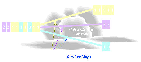
To begin with, ATM (also known as 'Cell Relay') acts just like Frame Relay in that ATM does not protect data from errors. ATM relies on user equipment error control, and therefore works well on digital lines with low bit error rates. The cells for one user are transmitted over a Permanent or Switched Virtual Circuit Connection (PVC or SVC) just like in Frame Relay or X.25. However, while in those two technologies the circuit had to be built in its entirety at subscription time (PVCs) or at connection time (SVCs), in ATM, the paths over which various circuit connections are made are prebuilt. This saves processing time both at the user-to-network interface (UNI) and network-to-network interface (NNI).
This also goes hand-in-hand with the carrier system of choice for ATM, SONET (Synchronous Optical Network), which defines user paths using its lines and sections of fiber.
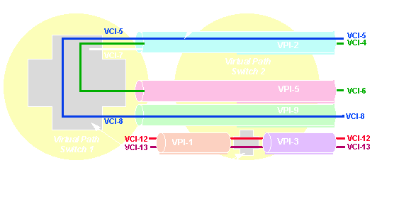
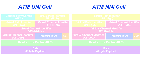
The cell header contains (among other things) a field of eight bits to define possible virtual paths at the UNI (256 physical destinations) and a field of sixteen bits to define up to 65,536 virtual circuits on each path.
At the NNI (in the network -- between switches) the number of virtual paths is increased to 4,096 (twelve bits) because it is assumed that the network will carry many more than just one user.
The two fields are called VPI (Virtual Path Identifier) and VCI (Virtual Circuit Identifier) respectively. A virtual connection (VC) will carry data, voice or video (not all simultaneously). Each type of traffic requires at least one unique VC.
The VC passes through nodes and over links/trunks, and at each node port it has buffers allocated for transmit and receive. The buffers are identified by VCIs and VPIs unique to the trunk. The VC therefore has a number of attributes which describe its usage:
The concepts are very similar to Frame Relay (or, for that matter, X.25). The 'sustainable cell rate' or SCR is called Committed Information Rate (CIR) in Frame Relay and Throughput Class in X.25. The VCI/VPI Cell Relay is what DLCI is in Frame Relay and LCN (Logical Channel Number) in X.25. Metering in ATM is done using a 'leaky bucket' or 'virtual scheduling' algorithm, just like in Frame Relay. Every VC is given a timed buffer at every switched port. The sustainable cell rate (SCR) is the ratio between the Committed Burst of Cells (Bc) and the time interval during which no more than Bc cells may be sent (Committed Time, Tc): SCR = Bc/Tc.
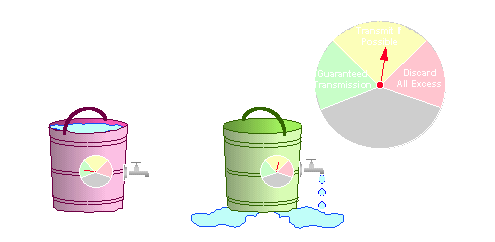
Typically, the customer may exceed Bc by an Excess Burst of cells (Be) during the same time (Tc), by using a second buffer of the same size as the first one. However, cells that exceed Bc are at risk: they are eligible for discard. There is a bit in the header called CLP (Cell Loss Priority) which, when set, indicates that the cell can be discarded by a congested node. Sound familiar? - Frame Relay has a DE (Discard Eligibility) bit -- The N. Erds from Frame Relay did not talk with the N. Erds from Cell Relay and we normal people have to learn new acronyms! If there is a hell, I want to banish the N. Erds there just for a month, then they can go to heaven (they deserve it); but during that month I would have the Hell Supervisor have them memorize as many new acronyms as we are subjected to. For that matter, graduation to heaven would be conditional: they would have to pass a test!
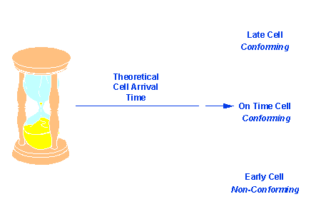
With virtual scheduling, a clock ticks at every node. The ticks act as a sort of pace counter, or metronome beat. Cells coming on or after the tick are not eligible for discard. Cells that come before the tick are arriving too soon, and so are eligible for discard.
In addition to these (VPI, VCI, CLP), the cell header contains a 'payload type' that describes what kind of information this cell carries - data or management (Operation And Maintenance - OAM) and whether the VC carrying it is congested or not, and a HEC or Header Error Control field which, with eight bits, provides enough redundancy to allow Forward Error Correction up to one bit. This makes the loss of cells due to errors less likely.
The HEC is also used for synchronization: switches learn what a cell period is by constantly identifying good HECs.
Finally -- remember I said there is a difference between the numbers of VPIs at UNI (User to Network Interface) and at NNI (Network to Network Interface)? The UNI cell uses only eight bits and the NNI uses twelve bits for the VPI. At UNI the four-bit difference makes up a field called Generic Flow Control (GFC). It is 'generic' because each piece of equipment may use it as it pleases (it's not defined yet). For example, if by magic all GFC bits are '0' that could mean 'user equipment, now you can transmit; there is no congestion'; if they become '1' that could mean 'stop transmitting; there is congestion on this VC'.
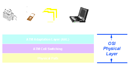
While the cells are docile little workers carrying information in their payload bit-times, some will get lost due to noise or equipment failure, others due to congestion. Therefore, various types of traffic generators with their different requirements have to carefully prepare or 'adapt' their messages for travel over the ATM network.
This is done in each case by a piece of software or firmware called AAL (ATM Adaptation Layer).
The AAL has two stages:
The CS assures the necessary error control and sequencing as well as the sizing of information. The SAR then chops the CS message into the 48-byte payload packets and attaches them to the five-byte header. There are five types of adaptation layer services, designated AAL1, AAL 2, etc. At the transmit node AAL1 prepares voice traffic, AAL2 prepares video traffic, AAL3 and AAL5 prepare connection-oriented data (TCP-like data) and AAL4 prepares connectionless data (SMDS or LAN-like) for cell relay switching. After the preparation stage, the message is delivered to the segmentation layer, where the cells are created and sent.
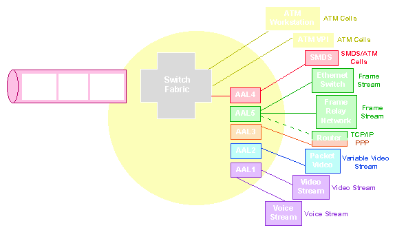
At the receive side the cells go through the reassembly layer and are passed to AAL1, 2, 3, 4, or 5 for the recreation of the original message. This message is then delivered to the video monitor, the voice receiver or the data process expecting it.
AAL3 and AAL5 are both intended for connection-oriented data. However, AAL3 is a complex, sophisticated preparer designed by a committee of the ITU - TSS (Telecommunications Standards Sector, formerly known as CCITT). AAL5 is much simpler and relies mostly on the fact that the network is error-free most of the time. AAL5 is also known as SEAL (Simple and Efficient Adaptation Layer) and is the creation of the ATM Forum, an organization of users, manufacturers and carriers that try to steer ATM services with common sense. Presently ITU-TSS is studying AAL5.
Now that I've filled your brains with acronyms, let me tell you really what the AALs are trying to do.
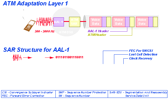
AAL1 is intended for voice traffic. Since voice traffic is error tolerant, no error control (CRC) is required. However, what is important in the case of voice transmission is that cells are received in the exact sequence in which they were sent, and that they arrive at a constant rate.
AAL1 assures sequence numbers. (If cells were scrambled, should you send the message 'Hello', the receiver might hear 'Ohell'.).
Also, one 48 byte cell may carry eight-bit voice samples (see the ISDN tutorial) from more than one source.
Since voice is transmitted synchronously, without delay, it is possible that by the time the voice transmitter has sent a few samples, the cell must leave partially empty. This type of service is called 'Streaming Mode Service'.
AAL1 is designed to handle this: it inserts sequence numbers in cells and identifies what portion of the cell carries voice and what portion carries nothing.
With video, not only do we need synchronous and sequencing, but we also need error checking codes (CRCs). And, since a screen may have a lot of pixel information, many cells may have to be used to transmit the whole screen; so we need to know where the screen starts and where it ends. That's why the cells are labeled as 'the first' or 'intermediate one' or 'the last'.
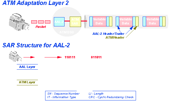
This way AAL2 can assure bandwidth-on-demand with a variable rate.
Think of video conferencing. Normally, speakers aren't very fond of public appearances and they sit frozen in one position moving only their lips. Occasionally something excites them and they make sudden body moves - then entire screens may change - but in their frozen position, very little bandwidth is required to transmit the lip movement. By labeling the cells of a message as 'first', 'intermediate' and 'last', AAL2 can transmit as little or as much as is needed.
Data transmission is of two kinds:
AAL3 and 5 are designed for connection-oriented service, and AAL4 for datagrams. Like AAL2 for video, both data services require error checking (CRC), sequencing, and identification of the cells as part of the message. In addition, some sort of indication has to be given to the receiver about the total length of the message, so an appropriate buffer size can be reserved for the message.
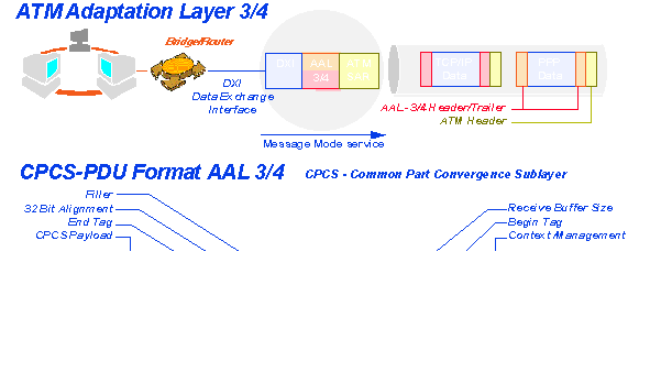
AAL3 is very similar to AAL2. The difference is in timing (AAL3 does not require synchronism between receiver and transmitter).
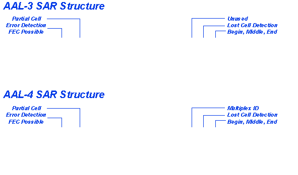
AAL4, in addition, must identify each cell as belonging to one datagram. So each cell is given a 'Multiplex Identifier' (a ten-bit field) for this purpose.
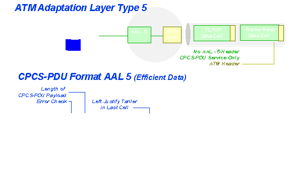
AAL5 does not bother to insert all this extraneous information into each cell. Instead, before the TCP or some other data message is chopped into cells, a 'trailer' is appended to that message, containing a 'length' indicator of two bytes (TCP segments can be 65,536 bytes long), a CRC error checking code for the whole message, and some bits signaling user-to-user (end-to-end) what this message is about (this is still under study and is to be used by each user equipment as it sees fit). Then this 'adapted' message is put through the chopper and the cells are sent.
Well, folks, let's see how all these layers and the different pieces of gear interact to make the cells move.
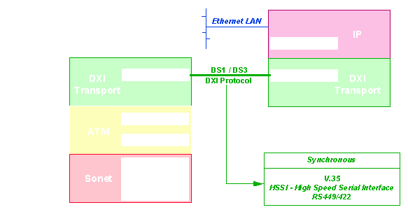
The data sources (bridges, routers) or the video and voice sources (like PBXs) run their usual software (for example TCP/IP). A special interface sends the message to be adapted to a specialized box generally called an ATM CSU/DSU (Customer Service Unit/Digital Service Unit). This box contains the Adaptation Layer and the Segmentation and Reassembly Layer, and the fiber or wire or microwave interface to SONET, T1 or T3 lines.
The interface between the Router and the ATM CSU must be fast and must ensure data transfer protection (error and flow control). There are a number of solutions for this:
Since ATM switches are fast and have a large throughput, multiport switches can be used as LAN emulators with broadband capabilities (multiple connections can exist simultaneously).
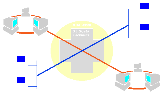
Departmental LANs are hooked up through bridges and routers to a central hubbing switch on ports that talk to these routers via ATM DSUs using DXI or via TAXI or ATMR interfaces.
One last 'technical' (boring) thing: Standards exist that define switched (on demand) ATM service. The networking scheme for this type of service is known as BISDN (Broadband ISDN) and it works conceptually very similar to ISDN (see that tutorial).
In ISDN, signaling (requesting services from the network) is handled via a dedicated data path called the D channel. In BISDN, signaling is handled through a common Virtual Circuit (reserved for each user) called the 'metasignaling' channel. The standard that shows how to signal is called Q.93B and is an ITU-TSS standard.
By the way, here are some useful standard numbers:
One last word: It would seem logical to use ATM whenever data, voice and video traffics are to be integrated. However, let's consider the cost per bit of voice transmission: at a cost of (let's say) 10 cents/minute, and at 64 Kbps (voice speed), a bit of voice would be sent at a cost of
10 cents / (60 seconds x 64,000 bits/second) = about 1/400,000 of a cent.
Remember that a voice line (analog) is a 4 KHz line, and to digitize voice we use 16 times more bandwidth (64 Kbps). Let's consider entertainment video (movies). To digitize a movie (a cable TV channel uses 6 MHz of bandwidth) we would need 16 times the 6 MHz, or 96 Mbps. Of course, with compression and other tricks, we may reduce the full-motion movie to rates of maybe 20 Mbps. If such a movie lasts about 100 minutes, we can say that 1 bit of entertainment video will cost:
$6 (this is what I would pay for the movie)/ 100 minutes x 60 seconds x 20,000,000 bps = 600 cents/60,000,000,000 x 2 bits = 1/200,000,000 cents/bit, or 1/200,000,000 of a cent.
500 times cheaper!!!
Do you think the carriers will be fools to mix voice and video traffic and give the user the opportunity to transmit voice bits over video circuits at prices 250 times lower? I don't think so!!
This is why, probably over the next few years we'll see video and data services over ATM, but voice will be kept separate.
However, in private networks, all traffic types will be mixed.
So long folks.
Yours,
Norm Al Dude
PS: By the way, I don't recall if I told you: Asynchronous Transfer Mode is called Asynchronous because traffic can come any time, statistically speaking. However, once it came, it's transmitted synchronously. Go figure!
PPS: You may want to look at some other publications that offer more information on ATM and related topics.
 Tutorial index
The tutorial index page lists other articles on the technology of data communications.
 Home
HomeReturn to the main DataComm-US index page.

Copyright © 1996 SCAN Technologies.
All rights reserved.
Authors: Dan Stern and Frank Mazella